Leave Your Message
Leave your message now to get your free sample and discount price
Leave your message now to get your free sample and discount price
A Lathe Insert may be small, but its geometry shapes the cut, the surface finish, and the pace of a turning job. Clamped into a toolholder, this replaceable cutting tip meets a rotating workpiece and removes material in controlled chips. Its grade, nose radius, and edge shape matter. So does the setup. A sharp insert cannot rescue a loose toolholder or an unsuitable cutting speed.
“An insert works best when its edge geometry, material grade, and cutting conditions suit the job,” says machining specialist Alex Morgan. The principle is simple. The choices are not. A machinist turning mild steel may select a different insert from one cutting stainless steel or cast iron. Chipbreakers help guide chips away from the workpiece, while coatings can improve wear resistance under suitable conditions. Yet no insert is universal. Even a proven setup may need adjustment when the machine, material batch, or cut changes.
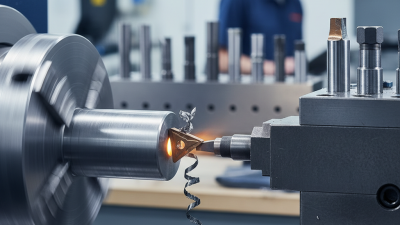
Picture a carbide tip cutting a bright spiral from a steel bar. Heat gathers near the edge; chips curl across the rake face. If the chip breaks cleanly and the edge remains stable, the setup is doing its work. Watch closely. A rough finish, rising tool wear, or tangled chips can signal a mismatch. These clues are useful, but they do not diagnose every problem on their own. This guide explains what a Lathe Insert is, how it removes material, and which practical factors help users choose and operate one reliably.
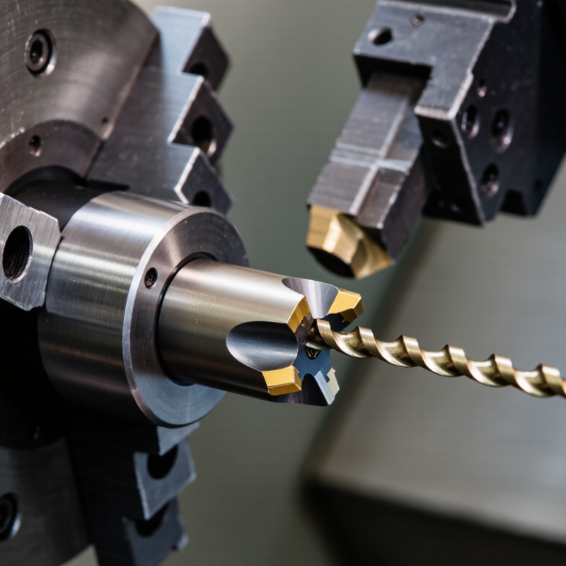
What Is a Lathe Insert and How Does It Work?
What a Lathe Insert Is
A lathe insert is a small, replaceable cutting tool mounted on a turning tool holder. It removes material as the workpiece rotates against its sharp cutting edge. Most inserts have several usable corners, so a worn edge can be changed quickly without replacing the entire holder.
The insert’s shape affects cutting access, strength, and surface finish. A triangular insert reaches tight shoulders, while a round insert handles interrupted cuts with greater edge strength. Its top surface may include a chip breaker, which guides hot chips away from the cutting zone. Coatings and carbide grades also help resist heat, abrasion, and repeated pressure.
In practical machining, insert selection depends on the workpiece, cutting speed, feed rate, and required finish. A machinist checks the holder, seats the insert firmly, and confirms its orientation before cutting. Small mistakes matter. An incorrect insert height can create vibration, poor accuracy, or a damaged edge. I have found that choosing a stronger insert is not always better; excessive edge strength can increase cutting force. The best choice often balances toughness, sharpness, and control. Even manufacturer data needs adjustment when the machine lacks rigidity or the material behaves differently than expected.
| Feature | What It Is | How It Works | Common Examples or Considerations |
|---|---|---|---|
| Lathe insert | A small, replaceable cutting tip mounted in a toolholder for turning operations. | As the workpiece rotates, the insert is fed against it and removes material to create a desired diameter, face, groove, or profile. | Often called an indexable insert because a fresh cutting edge can be presented by rotating or repositioning the insert. |
| Cutting edge | The sharp junction where the insert’s rake face meets its clearance face. | The edge penetrates the workpiece and shears off material as a chip. Cutting speed, feed, and depth of cut affect the load on the edge. | Edge strength and sharpness are selected according to the work material, operation, and required finish. |
| Insert body and cutting material | The insert’s substrate provides the shape and supports the cutting edge. | Hardness and heat resistance help the edge withstand cutting forces and temperature. Some inserts also have a wear-resistant coating. | Common cutting materials include cemented carbide, cermet, ceramic, cubic boron nitride (CBN), and polycrystalline diamond (PCD). Suitability depends on the workpiece material and cutting conditions. |
| Rake face and rake angle | The rake face is the surface over which the chip flows; rake angle describes its orientation relative to the cutting edge. | Rake geometry influences chip flow, cutting force, heat generation, and edge strength. | A more positive rake can reduce cutting forces but may leave a less robust edge; a stronger, more negative geometry may suit heavier cuts or harder materials. |
| Clearance face and clearance angle | The clearance face is the surface behind the cutting edge; its angle keeps the insert body from rubbing against the newly cut surface. | Proper clearance allows cutting rather than excessive rubbing, helping limit friction and heat. | The required geometry depends on the insert style, holder setup, and operation. |
| Nose radius | The rounded portion where the insert’s cutting edges meet at the tool tip. | It helps determine the surface finish and distributes cutting forces across the tool tip. | A larger radius can improve strength and finish under suitable conditions, but may increase radial forces or cause chatter on a less rigid setup. |
| Chip breaker | A groove, ridge, or shaped feature on the rake face, sometimes combined with a defined insert geometry. | It guides and curls the chip, helping control chip size and direction across a suitable range of feeds and depths of cut. | Chip control depends on the insert design and cutting conditions; a chip breaker cannot guarantee short chips in every application. |
| Insert shape and cutting edges | The plan-view shape and number of usable corners or edges. | After an edge wears or chips, the insert can often be rotated or turned to expose another usable edge, then replaced when its edges are exhausted. | Common shapes include round, triangular, square, rhombic, and trigon styles. The shape affects edge strength, access, and the profiles that can be machined. |
| Toolholder and clamping | The holder locates and secures the insert in the lathe tool assembly. | Clamping keeps the insert correctly positioned while cutting forces act on it. The holder also sets the tool’s orientation relative to the workpiece. | The insert and holder must be compatible in size, seating style, and cutting orientation; secure seating is essential for consistent machining. |
| Insert selection | The process of matching insert geometry and cutting material to the job. | Selection balances material compatibility, operation type, rigidity, cutting conditions, chip control, tool life, and surface-finish requirements. | Turning, facing, profiling, and grooving can require different insert geometries. Follow the insert maker’s cutting data and adjust for the actual machine and setup. |